Machine Design – Pneumatic Cylinder Assembly
Client:
University Project – GBDP module
Date:
May 2021
Overview
As part of the group business design project module, I was working in a team of 5 developing an on-site commercial sorting system for soft produce. Our chosen concept consisted of a series of actuated sliding drawers that held trays of fruit punnets that a pick and place machine would deposit the product into. Due to the capabilities of the pick and place machine, the trays had to be able to move to 3 decreet positions. My role within the team was developing the actuation system that would move the sliding drawers. Due to the point-to-point nature of the motion, the need for reliable operation in the harsh agricultural environment, and the food safety requirements that the machine must meet, I identified pneumatics as the technology of choice for this application. The greatest challenges in developing the actuation system were using standard pneumatic actuators to achieve intermediate positions in a reliable and cost-efficient way and developing a complete pneumatic circuit that meets both food hygiene safety and machine safety regulations. This was achieved using 4 major components: a compressor, a valve terminal, an air preparation unit, and a cylinder assembly. The cylinder assembly consists of two off-the-shelf Festo actuators mounted in series, they can be activated independently to give three discrete positions. Overall, the actuation system met most of the requirement including the numerous regulatory constraints by utilizing a high ratio of off-the shelf components.
Actuation System

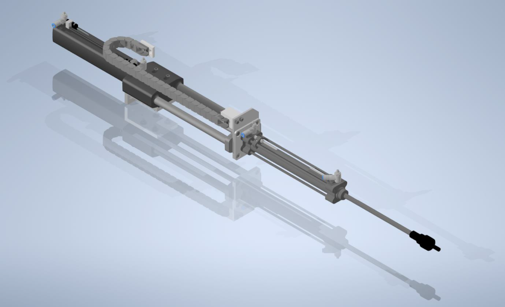
Actuator Assembly
The motion required to move the trays is achieved using the actuator assembly. Each assembly consists of two pneumatic actuators mounted in series. This configuration of actuators gives 3 discrete positions that the trays can be moved to. There are 8 actuator assemblies in the machine, one per tray (16 actuators total).
Valve Terminal
This component is used to control the switching of compressed air between the 16 pneumatic actuators. The valve terminal consists of 16 pneumatic valves mounted on a manifold (one valve per actuator) and each valve can be controlled individually via a single electrical connection to the valve terminal.
Air Preparation Unit
This unit consists of 4 components: a manual on/off valve, a pressure regulator with pressure sensor, an electrical on/off valve, and a soft start valve. This unit regulates the line pressure for the pneumatic system and provides several key safety features.
Compressor Unit
This unit consists of an air compressor, integrated cooling system, and multi-stage air filter and dryer. It provides the compressed air needed to drive the pneumatic actuators.
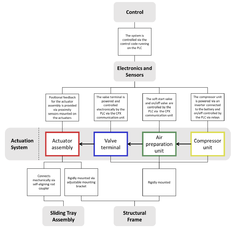
Interfaces with other subsystems
The diagram below show how the actuation subsystem interfaces with the other subsystems of the machine.
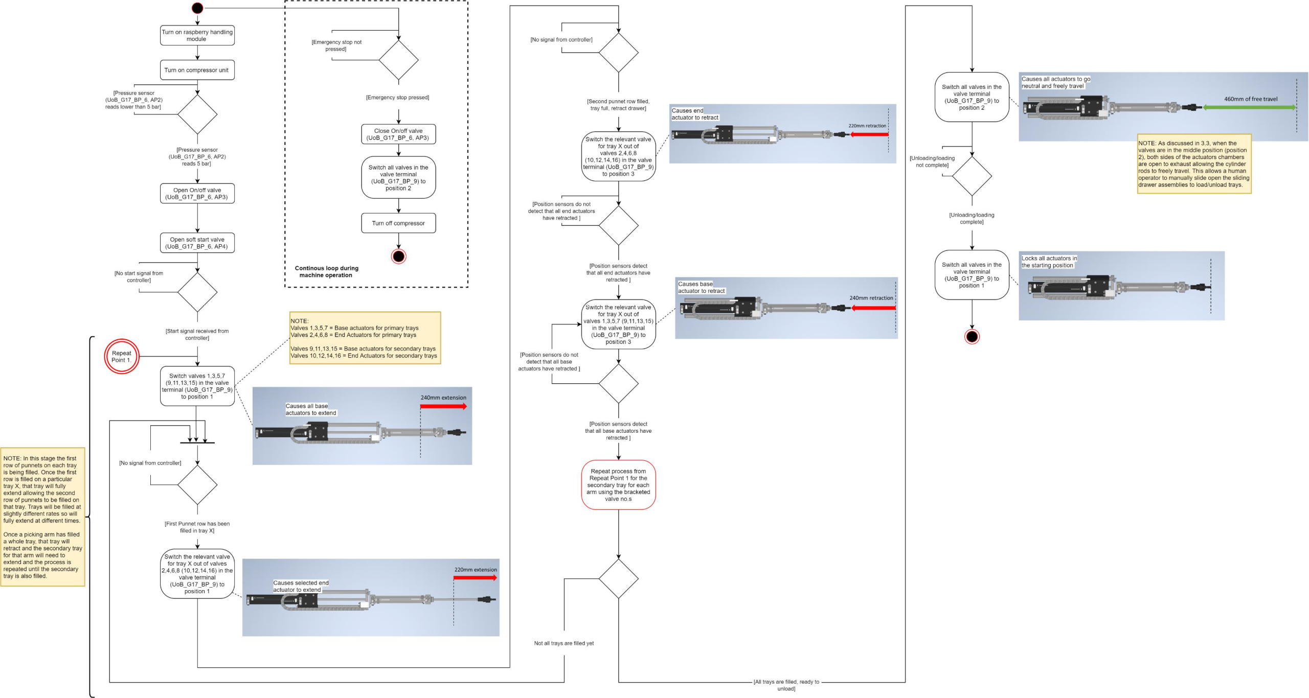
Sequence of Operation